I said I would do a little writeup of the software for the weather station earlier, and I realized that it would actually be good to do a little How-To about using an Xbee to wirelessly upload now software to an Arduino. While I’ll include a bit of explanation along the way, there will be (I hope) complete instructions for getting an Arduino Pro Mini working with wireless bootloading. Because I use Linux, that’s what I’ll describe. I also don’t use the Arduino IDE, preferring Emacs and GNU Make since that’s what I use for work and my other programming projects.
Background
The idea is that once you’ve gone wireless and have an Arduino hooked up to an Xbee somewhere, it’s a big inconvenience to have to hook it up to a USB cable every time you want to update the software its running. Since Xbees can act as a serial pipe, it should in principle be possible to just do the upload over that link, but in practice the default bootloader is not very robust to lossy radio links.
When I first tried to do this back in 2009, I came across this tutorial by Nate at Sparkfun. He wrote an alternative bootloader called sfxb (for SparkFun XBee, I assume) which checksums the uploaded data and can request retransmissions of bad packets. This way a few lost packets won’t kill the upload. The big drawback, at least for me, was that his uploader only worked for Windows.
Luckily another user, Alan Backlund, posted in a comment to the tutorial that he had added the upload protocol to avrdude, the normal program for programming AVR microcontrollers. You can easily compile this on Linux or Mac. I used his code for a while and it worked fairly well. I also tweaked the bootloader a bit to make it more robust.
Eventually I wanted to use Series 2 XBees. Series 1 XBees can be programmed to automatically pass digital lines, which means you can easily pass the Arduino reset line over the radio link, but Series 2 ones don’t do this. I also wanted to use the XBee in API mode, where you send explicit packets instead of just passing serial data. This is necessary if you want your XBee to talk to more than one remote node, since otherwise you can’t know where the data is coming from. This required a more extensive rewrite of the avrdude sfxb programmer. (If you want to learn more about how XBees work and how they can be used to make a distributed network for small amounts of data, the book “Building Wireless Sensor Networks” by Robert Faludi is a good start.)
At this point, I have a pretty well set up system that I’m using to have my Linux server get sensor data from 3 different remote XBees. Using my software, I can also upload new code to one remote Arduino without disturbing the links to the others. I’m pretty happy with the setup and I figure it can be used fruitfully by others, so I figured I should write a detailed description with links to the code.
So, if you’re interested in uploading code to an Arduino over an XBee link and in general interfacing with multiple remote XBees, read on. This is going to be a pretty long and detailed post, but I hope by the end of it you’ll at least be able to get your code uploaded. The rest of the code may have to wait for another post.
Overview of Atmega bootloading – Fuses and Self-programming
There are two different ways of writing programs to the flash memory inside an ATmega chip.
The first is to write data directly to the memory, normally using the SPI serial bus. If the reset and SPI clock pins are held low when the device is powered up, a special instruction sent over the SPI bus will make the device enter programming mode, where data sent over the SPI bus gets written directly to the flash memory.
The second method is by “self-programming”, where the processor executes a program that writes data to its own memory. The flash memory on the Atmega 328P is divided into two different areas: the boot loader section and the application section. Code executing in the boot loader section can issue programming instructions that write data to the application section, but the boot loading section can only be modified by the first method: direct programming over the SPI bus. The size of the boot loading section can be set using programmable fuse bits to anything from zero to 4096 bytes. The remaining part of the 32K flash memory is available for applications.
A boot loader is a program that resides in the boot loading section which reads data in some way (normally over the serial connections) and writes it to the application section. The boot loader is entered automatically when the device is powered up or reset. If it detects incoming data, it proceeds to read it and write to the flash memory. If there is no incoming data it just jumps to the application section and starts the normal program.
Chapter 23–25 of the datasheet describes all the details of how self-programming or external programming works. If you want to learn the details, I encourage you to read them carefully.
Installing the bootloader
From the above, it’s clear that the normal way Arduino programs are uploaded to the chip can not be used to update the bootloader — the bootloader cannot change its own code since it’s located in the boot loading section. (And even if it could, it would overwrite itself part way through.) The bootloader must be programmed using the SPI bus (the 6 “ICSP” pins on a standard Arduino footprint used for this are nothing more than the SPI, reset, and power pins.)
To write the programming instructions, you need an external “programmer” to handle the SPI communication. I use Sparkfun’s “Pocket AVR programmer”, which is just an ATtiny microcontroller programmed to interface between the USB port and the SPI bus. It’s only $15 and has been totally reliable for me.
In principle you should be able to write an Arduino program yourself to write the SPI instructions yourself, which might be a fun project if you really want to learn how it works. Sparkfun has an article about programming bootloaders, too.
Step 1: Hooking up the Arduino
Now let’s get practical! The Arduino Pro Mini is a low-cost Arduino clone from Sparkfun. Because it’s just a bare board, it’s much cheaper than a normal Arduino, but it also means you need to set some stuff up to be able to use it. It’s perfect for embedded projects where you need an Arduino to control something in a permanent installation. It’s what I used for the Weatherstation and in my (yet-to-be-described) project to talk to the inverter for our solar system. Sparkfun has a tutorial describing how to set it up. It comes in 3.3V and 5V versions, and the 3.3V is good for hooking up to an XBee since those run at 3.3V, too.
The first thing to do, after soldering some headers to the Pro Mini, is to hook it up to the AVR programmer so we can upload the bootloader to it. This involves connecting 6 wires, VCC, GND, reset, and the 3 SPI pins: MOSI, MISO, and SCK. The pins are clearly labeled on the back of the connector for the programmer. For hooking them up to the Arduino, I made a little wire myself so I don’t have to figure out which pins are which every time, but you can also use breadboard wires.
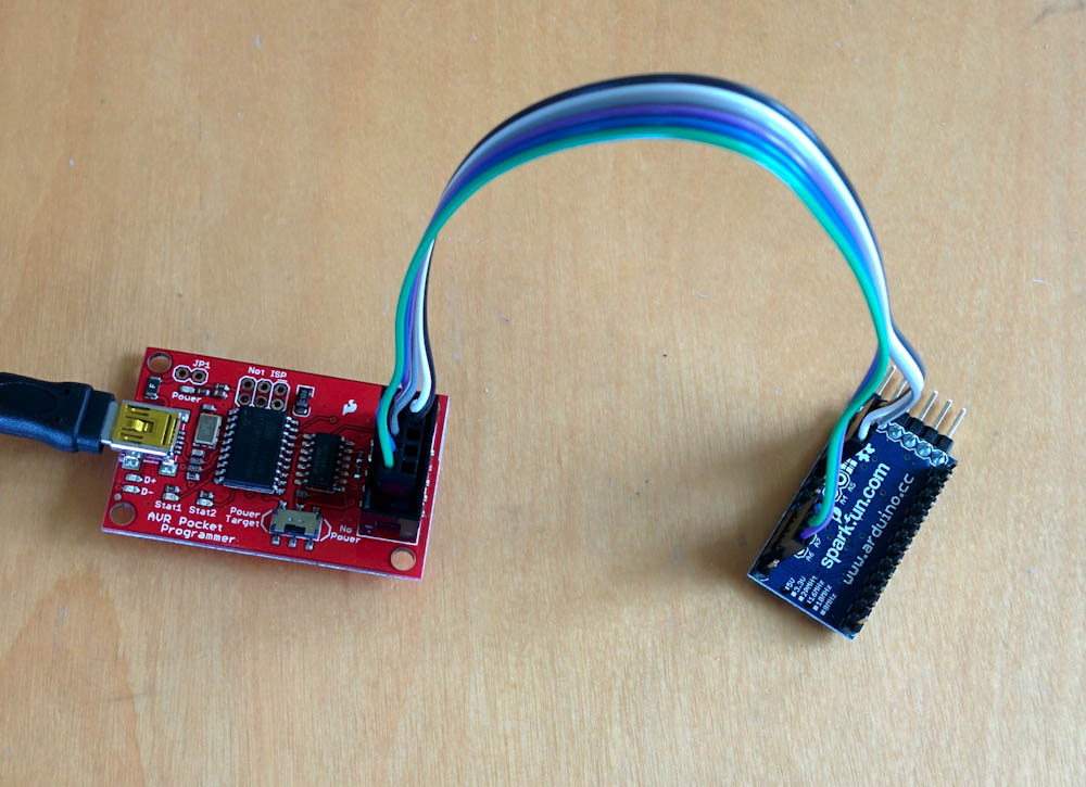
The Arduino Pro Mini on the right, hooked up to the “Pocket Programmer” on the left.
The six pins on the programmer connect to the Arduino in two groups of three, one for power/reset and one for the SPI pins. The picture below shows which are which.
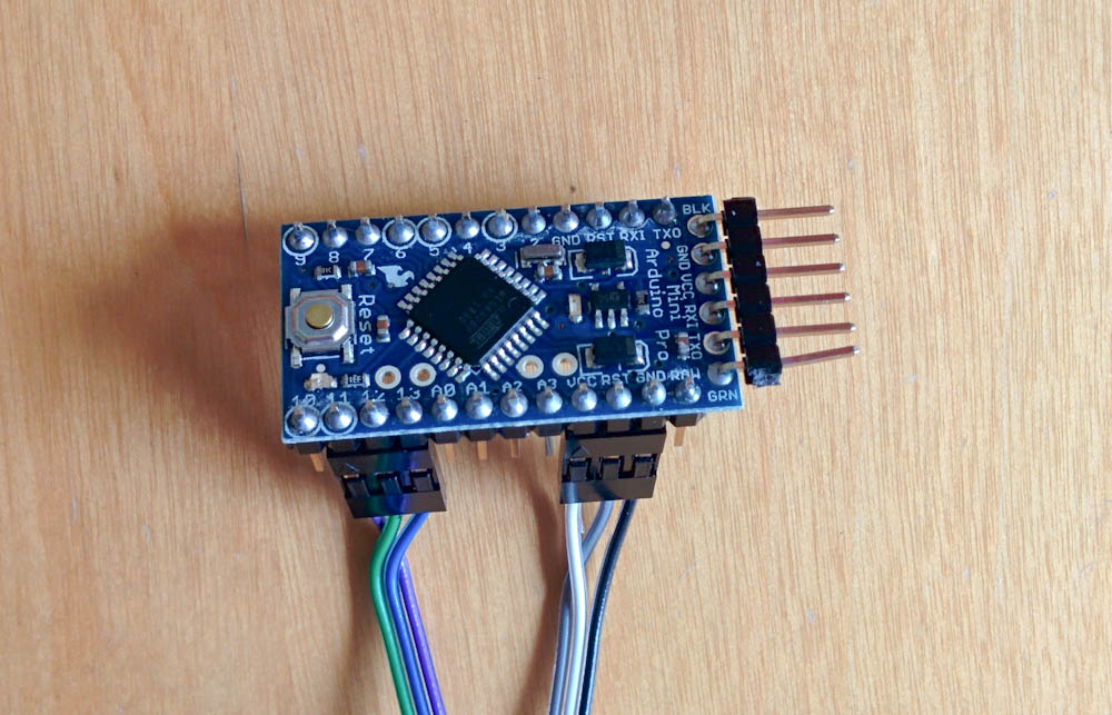
This shows the six pins that are connected to the bootloader. The thee on the right are VCC, GND, and reset. The three on the left are the SPI pins: MOSI (pin 11), MISO (pin 12) and SCK (pin 13).
Once it’s hooked up, the red power LED on the Arduino board should light up if you plug the programmer into a USB port.
Step 2: Setting up the avr build environment
In order to be able to compile Arduino programs, we need to set the build environment up first.
Depending on your system, this might require some fiddling, but the good news is that you only have to do this once.
The first step is to install the avr-gcc toolchain so you can compile AVR code. Depending on your Linux distribution, there are probably packages for avr-gcc and avr-libc. (If there isn’t, you have to build them yourself, which is beyond the scope of this tutorial.) Once you have these installed, you should be able to type avr-gcc --version in a shell and see the gcc print out its version. On my machine, it responds
avr-gcc (Fedora 4.6.2-1.fc16) 4.6.2
Once this works, you need to download and build avrdude. This will be used to program the bootloader onto the Arduino but also to upload the programs over the XBee once we’re done with all of this.
Programming the bootloader can be done with the normal avrdude but since you’ll need the version with the sfxb bootloader to actually upload programs later, you might as well get it compiled right now. You get it from my Bitbucket repository by doing git clone git@bitbucket.org:lutorm/avrdude.git.
Building and installing avrdude is done with the GNU autotools, if you’ve ever compiled code on Unix you’ve probably run across it before. The file INSTALL has instructions, but briefly they consist of doing
./configure --prefix=$HOME

make install
If all goes as planned, this will install avrdude in the bin directory under your home directory. (Omitting the –prefix argument from configure will make it want to install it in the system-wide /usr/local directory. I keep it in my home dir. Then add $HOME/bin to your PATH variable so the shell will find it.
If avrdude doesn’t build properly, you’ll have to figure out why. There shouldn’t be any problems, but sometimes if there are it’s probably because your system has some file in a slightly different place.
Step 3: Compiling the bootloader
Once avrdude works, it’s time to download the sfxb bootloader. You can get it (and all my other Arduino code) from by Bitbucket repository by doing git clone git@bitbucket.org:lutorm/arduino.git. In the arduino directory you’ll find a directory called “sfxb_bootloader”. Go there.
The directory contains two files, the Makefile and sfxb_bootloader.c. There are a few things you need to make sure are set up correctly before compiling the code.
The first is the clock frequency of the Arduino: By default, the code is set up for the 8MHz 3.3V Arduinos, but if your clock speed is different, you need to change this line in the Makefile: F_CPU = 8000000 and this line in the bootloader source: #define CPU_SPEED 8000000LL so they reflect your processor speed. If your Arduino doesn’t use an ATMega328P, you’ll also have to change the MCU line.
The third thing that may have to be adjusted is the LDSECTION line. This determines where in memory the bootloader will be located. The value in my code is byte address 0x7c00, which is appropriate for a 512-word boot loader size (see Table 24.8.16 in the datasheet.) The sfxb bootloader code just barely fits inside of this, so if you add anything to it, you’ll likely have to increase the size of the boot leader section to 1024 words, costing you 1K bytes of program space.
The stock Arduino bootloader is bigger than this, so Arduinos generally do not come programmed with a 512-word boot loader size. This corresponds to fuse values BOOTSZ0=0, BOOTSZ1=1. Before we can program the bootloader, we have to adjust the fuse bits to set the BOOTSZ bits correctly. If this isn’t done, the Arduino will jump to the wrong address when it boots, and will either start in the middle of the bootloader or into the application code. The result will be that the bootloader may appear to work initially, but will either not write to memory correctly or will cease to work after code is uploaded to the boot address.
There is a handy fuse calculator at engbedded.com that can help you interpret the fuse values. To read the current fuse values with avrdude, do
avrdude -c usbtiny -p atmega328p -U lfuse:r:-:h
(If you don’t use the pocket programmer, you have to change usbtiny to whatever is appropriate for your programmer. If it doesn’t work, it’s also possible you’ve hooked up the Arduino to the programmer incorrectly. Double-check the connections.)
The command should have spit out the current value of the lfuse bits in hex to the screen, along with some diagnostics. Do the same with hfuse and efuse and use the fuse calculator to see what fuse bits this corresponds to. The BOOTSZ fuse bits are in hfuse. Set those to the values above and see what fuse value this corresponds to. For my Arduino Pro Mini, the correct hfuse value is 0xdc. This corresponds to BOOTRST programmed (which means the Arduino will jump to the boot loader at reset) and SPIEN programmed (which enables SPI programming) along with the correct size boot loader section. Now write the fuse value to the Arduino by doing
avrdude -c usbtiny -p atmega328p -U hfuse:w:0xdc:m
A word of caution: It is possible to make the Arduino unusable by writing the wrong fuse bits. For example, if you clear the SPIEN fuse bit, you can no longer program it using the serial programmer. Changing the clock values in the lfuse to something incorrect can also make it not run. I think there are ways to fix this, but you may not have the equipment to do it, so be careful. Double-check the command before writing the fuse bits to make sure you’re writing the correct value to the correct fuse byte.
We are now just one step away from programming the bootloader. Go to the sfxb_bootloader directory in my arduino repo and do make. Hopefully this completes without error. Now do make program_serial. If it’s all hooked up correctly, the LEDs on the programmer should start blinking like crazy and avrdude should show the progress first uploading and then verifying the program being written.
Once avrdude is done, you should see the LED on the Arduino double-blink every couple of seconds. The double blink is the sign that the bootloader is running, and since there is no other code on the Arduino, it’ll just run over and over again. Once you get to this point, the hardest part is over!
I made a short video showing how the upload and the boot loader is supposed to work:
The sfxb protocol
Now that the bootloader is written to the Arduino, what do we need to do to upload code to it?
The first thing the bootloader does, as we saw in the video, is blink the LED twice. After that it sends a single character 0x05 over the serial port and waits for a response. If it gets a character 0x06 as response, it starts waiting for a new program to be uploaded. If anything but a 0x06 is received, or if nothing is received for a certain time (currently programmed to be 300 character periods), it jumps to the start of the application section and starts the normal program.
Uploading a new program happens in chunks. For each chunk, the bootloader sends the character ‘T’, meaning it’s ready for a transfer, and waits for a response consisting of a ‘:’, the number of bytes in the chunk (as a byte), the 16-bit address of the start of the chunk, and an 8-bit checksum of the following data. It then waits for the announced number of bytes of data to be received.
After the chunk is received, the data is compared against the checksum, and if it passes, the data is written to the flash and the LED flashed briefly. If the checksum test failed, it responds with a character 0x07, meaning the uploader needs to repeat the chunk (and double-flashes the LED), otherwise it sends a ‘T’ and the process starts over with the next chunk.
The end of the upload is signaled by sending the character ‘S’ as the size of the next chunk, the receipt of which makes the bootloader exit flash programming mode and jump to the start of the freshly-downloaded program.
This is a pretty simple scheme, but has proven to be quite robust. If data is corrupted in transmission, the bootloader will just ask for a repeat of the data over and over again until it gets a correct chunk. It might take a while, but eventually the data should get across. The only time-sensitive part of the negotiation is that the initial exchange of 0x05/0x06 has to be received by the bootloader before it starts the normal program.
Step 4: Setting up the XBees
Ok, so now that we know how the bootloader works, what do we need to do to get this working using XBees? I’m going to assume you know how to configure the XBees (or know how to google for it.) There are only a few things to make sure:
- While so far everything we’ve done is agnostic about how you hook the Arduino up, the avrdude uploader that we will use only works with Series 2 XBees. (I suspect it wouldn’t be that hard to get it to work with Series 1 as well, but I don’t use them.)
- The remote XBee (the one hooked up to the Arduino), must use AT (not API) firmware. It can use either “Router” or “End device” firmware. (A router will pass messages to other XBees, but an end device will use quite a bit less power. Unless you have a power constraint, make it a router.) It must also be configured for 19200 baud, because that’s the speed the bootloader uses to talk over the serial port. (The only way I know to update the firmware is to use X-CTU on a Windows machine, if you don’t have a Windows machine you need to figure out a different way of doing this.)
- While in X-CTU (or however you are configuring the XBees), write down the 64-bit address of the remote XBee (commands SL and SH). You need this address so you can tell avrdude where to send the upload in Step 5.
- All XBees must obviously be set up to use the same PAN ID, otherwise they won’t talk to each other.
- The reset pin on the Arduino must be hooked up to the DIO3 pin on the remote XBee. You don’t need a capacitor on the line, but it doesn’t hurt either.
- The local XBee (the one hooked up to whatever is going to be sending the programs) must use “Coordinator” API firmware. It can be configured at whatever speed you want, but I use 57600 so that’s what my Makefiles are set for.
- Make sure any XBees with router firmware are set with JV=1. (This means that whenever they are powered on, they will search for a coordinator. If you leave this at 0, they will remember the channel they found the coordinator on last time, so if the coordinator is ever restarted, they won’t find it at its new channel.)
If you read the SparkFun tutorial I linked to at the beginning of this page, you might have noticed that what they did was connect the DIO3 pin on the local XBee to the RTS pin on whatever you use to connect the XBee to a USB or serial port. This works because Series 1 XBees (which that tutorial used) can use the digital input/outputs to pass binary signals. If the input pin goes low on one radio, it’ll send a command to the other one to set the pin low. That way you can “pretend” that the reset line on the Arduino is connected directly to the RTS pin, which is how an Arduino is “normally” reset when you upload a new program using a USB cable.
The Series 2 XBees, however, do not have this binary line passing capability, so to reset the remote Arduino we’re going to have to send explicit commands to bring the DIO3 pin low and then high to start the bootloader. Avrdude does this for us.
Avrdude and the sfxb programmer
We are finally at the point where we can try uploading a program to the Arduino. While you can compile and invoke avrdude any way you want, this will describe doing it with the Makefiles I’ve set up for my projects.
Step 5: Uploading a program
For the purpose of this tutorial, let’s upload my project called “boiler_logger” to the Arduino. What it does isn’t really relevant right now, but it’ll serve as a test that everything works.
Go to that directory in the checkout of my Arduino repo. The Makefile in that directory looks like this:
TARGET = boiler_logger

ARDUINO_LIBS = OneWire OneWiretemp memory version XBee PID float16 serial_data
MCU = atmega328p
F_CPU = 16000000
ARDUINO_PORT = /dev/ttyUSB*
#ARDUINO_PORT = /dev/tty.usb*
AVRDUDE_ARD_PROGRAMMER = sfxb_api
AVRDUDE_ARD_BAUDRATE = 57600
AVRDUDE_EXTRA_OPTS = -x dest=0x0013a200409eda5b -v -v
include ../arduino.mk/Arduino.mk
The two first options specify the names of the resulting files and which libraries (under the libraries directory) that should be compiled along with the program. The next options are the customary specifications of which microcontroller and which clock frequency the target is for.
ARDUINO_PORT specifies the serial port the local XBee is attached to. On Linux, if you use an FTDI USB adapter, this will be something like /dev/ttyUSB0 which is the default selection. On a Mac, it’ll likely be something like /dev/tty.usb-blahblahblah, which is the second, commented out option. The AVRDUDE_ARD_PROGRAMMER specifies we want to use the sfxb bootloader and that the local XBee is running API firmware. The AVRDUDE_ARD_BAUDRATE should be set to the baud rate of the local XBee.
The interesting option is AVRDUDE_EXTRA_OPTS, which passes arbitrary extra options to avrdude. The -x dest=0x0013a200409eda5b specifies the 64-bit hex address of the remote XBee. Since avrdude must generate API commands addressed to the remote XBee to send data to it, it needs to know this address.
You should now change the F_CPU to the clock speed of your Arduino and set the destination address to the 64-bit address of your remote XBee that you wrote down in the previous step.
Once that is done, do “make” and if there are no errors, “make upload”. Avrdude should send commands to reset the Arduino, and if the handshake succeeds, you should then start seeing messages like “device successfully acked page xxxx”.
If the upload is successful, the Arduino should now start sending stuff back over the XBee, so if you open the /dev/ttyUSB or whatever port the local XBee is connected to and hit the reset button on the Arduino, you should see the message “Patrik’s boiler logger booting …” and then it’ll probably complain about a bunch of stuff… whatever, that means it’s all working and you’re now good to start uploading your own code!
Troubleshooting
If you’ve followed these instructions exactly, there really shouldn’t be any problem, but if it doesn’t work, here are some things to check:
- Does the Arduino reset when you start avrdude? You should see the LED double-blink right away when you give the command. If not, either you didn’t wire the reset up to DIO3 or it’s not getting the reset command. Try measuring the DIO3 pin on the XBee and make sure it toggles. You can also hook the remote XBee up directly to the serial port and give it the manual commands to toggle the pin (“ATD3 4” followed by “ATD3 5”) and make sure that resets the Arduino. (Remember the remote XBee should be set for 19200 baud.)
- If the Arduino resets, but avrdude says that it got something but 0x05, that likely indicates that the Arduino bootloader wasn’t compiled with the correct
F_CPU/CPU_SPEED. You should be able to plug the Arduino in directly to your serial port and see it send an endless stream of 0x05’s at 19200 baud. If not, go back and double check the settings you used when you compiled the bootloader. - If the upload starts but hangs with repeated “device requests retransmission of page xxxx”, the radio link may be too bad. When starting out, keep the XBees near each other to eliminate any reception problem.
- If the upload appears to complete correctly, but the Arduino keeps running the endless bootloader anyway (LED double-blinking every 2 seconds or so), the bootloader likely couldn’t write to the memory. Try plugging the Arduino back into the serial programmer and read back the contents of the flash mem with avrdude using
avrdude -c usbtiny -p atmega328p -U flash:r:flash.hex:iand see what the memory looks like. If the beginning of the file is all FF’s until you get to the bootloader at word address 0x3e00, the bootloader wasn’t allowed to write to the flash mem. This indicates that either the fuses aren’t set correctly, or theLDSECTIONwas set incorrectly in the Makefile for the bootloader. You’ll have to start over and double check those. - If the upload succeeds the first time, but not on subsequent attempts (and there’s no double-blink when you reset the Arduino), this indicates the boot reset vector was overwritten with application code. The can be caused by the same errors as the previous symptom.
So that’s pretty much it. If you’ve stayed with me this far, I hope you’re now set up for wireless bootloading. Like I said at the beginning, I’ve found this to be super useful and hopefully it’ll be as useful for others. When I get time, I’ll write a second part describing the Python code I’ve written to communicate with the individual remote XBees. This code is built on top of the python-xbee module and generates “virtual serial ports” for each of the remote XBees so you can talk to them independently. But this writeup is long enough already.
If you have any questions, or if you find any bugs in the bootloader or avrdude code, please send me an email at code@familjenjonsson.org. Happy uploading!
Does it work with arduino uno R3 ?
I’ve never tried it, but since you can program the Atmega328 using the ICSP header I would think so, as long as the extra ATmega16U2 isn’t interfering with the communications over the port. iIt doesn’t seem like the best choice if you want to hook it up to an XBee, though, since the XBee talks serial, not USB.
Thank you for your reply,
Yeah, you are right. As long as it is Atmega328, it should probably work. I won’t certainly use the UNO board. My question was a bit different. I have seen many people use Arduino Dumilanove firmware for wireless programming with XBee. So my concern was is there any specific reason why Uno firmware can not be used, or it is simply a matter of choice, any of the board can work?
Pingback: byufan.net » Blog Archive » Arduino Wireless Bootloading Using Series 2 XBees and XBeeBoot
So 7 years after writing this post I realized it’s incorrect. It states that the boot loader can not write to the boot section of the flash, but this is not true. I just attempted to boot load a too-long hex file and the bootloader overwrote itself. Turns out that there are “boot lock bits” that determine where the bootloader can write. (Having the bootloader be able to overwrite itself is apparently a “feature” where it can remove itself after having loaded some code, should you want to make it a once-only operation.)
The correct avrdude incantation to set the boot lock bit that prevents the bootloader from overwriting itself is:
avrdude -c usbtiny -p atmega328p -U lock:w:0x2f:m